
The General purpose 16x2 or 16x1 char LCD are very easy to interface with any microcontroller , and these lcd are really very cheap and thoroughly available in the whole world. Once you learn how to interface it, it will be the easiest and very reliable output device used by you! More, for micro controller based project, not every time any debugger can be used. All the LCD displays use the same, or any one of the IC s based upon the architecture introduced by Hitachi.
This component is specifically manufactured to be used with microcontrollers, which means that it cannot be activated by standard IC circuits. It is used for displaying different messages on a miniature liquid crystal display. The model described here is for its low price and great capabilities most frequently used in practice. It is based on the HD44780 microcontroller (Hitachi) and can display messages in two lines with 16 characters each. It can display all the letters of alphabet, Greek letters, punctuation marks, mathematical symbols etc. It is also possible to display symbols made up by the user. Other useful features include automatic message shift (left and right), cursor appearance, LED backlight etc.
Pin Configuration

LCD Memory
LCD display contains three memory blocks:- DDRAM Display Data RAM;
- CGRAM Character Generator RAM; and
- CGROM Character Generator ROM.
DDRAM Memory
DDRAM memory is used for storing characters to be displayed. The size of this memory is capable of storing 80 characters. Some memory locations are directly connected to the characters on display.Everything works quite simply: it is enough to configure the display to increment addresses automatically (shift right) and set the starting address for the message to be displayed (for example 00 hex).
Afterwards, all characters sent through lines D0-D7 will be displayed in the message format we are used to- from left to right. In this case, displaying starts from the first field of the first line because the initial address is 00 hex. If more than 16 characters are sent, then all of them will be memorized, but only the first sixteen characters will be visible. In order to display the rest of them, the shift command should be used. Virtually, everything looks as if the LCD display is a window which shifts left-right over memory locations containing different characters. In reality, this is how the effect of the message shifting over the screen has been created.

This is a sort of RAM memory so that data can be written to and read from it, but its content is irretrievably lost when the power goes off.
CGROM Memory
CGROM memory contains a standard character map with all characters that can be displayed on the screen. Each character is assigned to one memory location:
What is ASCII? From their inception till today, computers can recognize only numbers, but not letters. It means that all data a computer swaps with a peripheral device has a binary format even though the same is recognized by the man as letters (the keyboard is an excellent example). In other words, every character matches a unique combination of zeroes and ones. ASCII is character encoding based on the English alphabet. ASCII code specifies a correspondence between standard character symbols and their numerical equivalents.

CGRAM Memory
Apart from standard characters, the LCD display can also display symbols defined by the user itself. It can be any symbol in the size of 5x8 pixels. RAM memory called CGRAM in the size of 64 bytes enables it.Memory registers are 8 bits wide, but only 5 lower bits are used. Logic one (1) in every register represents a dimmed dot, while 8 locations grouped together represent one character. It is best illustrated in figure below:

Control and display commands

Outline
Now the instruction can be divided mainly in four kinds
1) Function set instructions
2) Address set instructions
3) Data transfer instructions with internal RAM
4) Others
Details of the Instructions
1) Read Data from RAM
RS | R/W | DB7 | DB6 | DB5 | DB4 | DB3 | DB2 | DB1 | DB0 |
1 | 1 | D7 | D6 | D5 | D4 | D3 | D2 | D1 | D0 |
Read 8bit binary data from DDRAM/CGRAM
The selection of RAM is set by the previous address set instruction. If the address set instruction of RAM is not performed before this instruction, the data that is read first is invalid, because the direction of AC is not determined. If the RAM data is read several times without RAM address set instruction before read operation, the correct RAM data from the second, but the first data would be incorrect, as there is no time to transfer RAM data. In case of DDRAM read operation, cursor shift instruction plays the same role as DDRAM address set instruction; it also transfers RAM data to the output data registers.
After read operation, the data address counter is automatically increased or decreased by 1 according to the entry mode. After CGRAM read operation, display shift may not be executed properly.
*In case of RAM write operation, AC is increased or decreased by 1 like that of the read operation. In this time AC indicates the next address position, but the previous data can only by the read instruction.
2) Write data to ram
RS | R/W | DB7 | DB6 | DB5 | DB4 | DB3 | DB2 | DB1 | DB0 |
1 | 0 | D7 | D6 | D5 | D4 | D3 | D2 | D1 | D0 |
Write binary 8bit data to DDRAM/CGRAM. The selection of CGRAM or DRAM is set by the previous address set instruction; DDRAM address set, CGRAM address set. RAM set instruction can also determine the AC direction to RAM.
After write operation, the address is automatically increased or decreased by 1 according to the entry mode.
3) Read Busy Flag and Address
RS | R/W | DB7 | DB6 | DB5 | DB4 | DB3 | DB2 | DB1 | DB0 |
0 | 1 | BF | AC6 | AC5 | AC4 | AC3 | AC2 | AC1 | AC0 |
By making this read out operation, it can be determined if the LCD is performing some internal operation or not. If Busy Flag (BF) is high, some internal operation is going inside the LCD at that particular moment. To perform further operation the data source (e.g. micro controller) must wait for the BF to go low. Here, the address counter value can also be read.
4) Set DDRAM Address
RS | R/W | DB7 | DB6 | DB5 | DB4 | DB3 | DB2 | DB1 | DB0 |
0 | 0 | 1 | AC6 | AC5 | AC4 | AC3 | AC2 | AC1 | AC0 |
Set DDRAM address to AC, this instruction makes DDRAM data available from MPU. In 1-line display mode, DDRAM address rangers from “00H” to “4FH”. In 2-line display mode, DDRAM address in the first line ranges from “00H” to “27H”, and DDRAM address in the 2nd line is from “40H” to “67H”.
5) Set CGRAM address
RS | R/W | DB7 | DB6 | DB5 | DB4 | DB3 | DB2 | DB1 | DB0 |
0 | 0 | 0 | 1 | AC5 | AC4 | AC3 | AC2 | AC1 | AC0 |
Set CGRAM address to AC. This instruction makes CGRAM data available from MPU.
6) Function Set
RS | R/W | DB7 | DB6 | DB5 | DB4 | DB3 | DB2 | DB1 | DB0 |
0 | 0 | 0 | 0 | 1 | DL | N | F | X | X |
DL: Interface data length control bit
DL=’1’ means 8bit mode of data transfer.
DL=’0’ means 4bit mode of data transfer
When 4 bit mode is activated, the data needs to be transferred in two parts, first higher 4bits, and then lower 4 bits.
N: display line number control bit
N=’1’ will allows to characters to display in 2-lines
N=’0’ will allows to characters to display in the first line only
F: display font control bit
F=’0’ will use 5×8 dots format display mode
F=’1’ will use 5×11 dots format display mode
7) Cursor or display Shift
RS | R/W | DB7 | DB6 | DB5 | DB4 | DB3 | DB2 | DB1 | DB0 |
0 | 0 | 0 | 0 | 0 | 1 | S/C | R/L | X | X |
Without writing or reading the display data, shifting right/left cursor position or display.
This instruction is made to correct or search or display data. During 2-line display mode, cursor moves to the 2nd line after the 40th digit of the 1st line.
When displayed data is shifted repeatedly, each line shifts individually.
When display shift is performed, the contents of the address counter are not changed.
8) Display On/Off Control
RS | R/W | DB7 | DB6 | DB5 | DB4 | DB3 | DB2 | DB1 | DB0 |
0 | 0 | 0 | 0 | 0 | 0 | 1 | D | C | B |
This instruction controls Display, Cursor and cursor blink.
D: Display On/Off control bit
D=’1’ means entire display is turned on
D=’0’ means entire display is turned off. But Display data remains in DDRAM.
C: cursor On/Off control bit
C=’1’ turns on the cursor
C=’0’ turns off the cursor. But I/D register retains the data
B: Cursor blink On/Off control bit
B=’1’ makes cursor blink periodically.
B=’0’ stops the cursor to blink and cursor looks steady if the Cursor is turned on.
9) Entry Mode Set
RS | R/W | DB7 | DB6 | DB5 | DB4 | DB3 | DB2 | DB1 | DB0 |
0 | 0 | 0 | 0 | 0 | 0 | 0 | 1 | I/D | SH |
This instruction sets the moving direction of cursor and display.
When I/D= ’1’ cursor moves to the right and DDRAM address is increased by 1.
When I/D= ’0’ cursor moves to the left and DDRAM address is decreased by 1.
CGRAM operates in the same way in this setting.
10) Return Home
RS | R/W | DB7 | DB6 | DB5 | DB4 | DB3 | DB2 | DB1 | DB0 |
0 | 0 | 0 | 0 | 0 | 0 | 0 | 0 | 1 | X |
This instruction sets the address counter to ‘00H’, and returns the cursor to the first column of first line. And if display is shifted previously, this instruction shifts this too. The DDRAM contents don’t change in this instruction.
11) Clear display
RS | R/W | DB7 | DB6 | DB5 | DB4 | DB3 | DB2 | DB1 | DB0 |
0 | 0 | 0 | 0 | 0 | 0 | 0 | 0 | 0 | 1 |
Clear all the display data by writing “20H” (ASCII code of ‘space’ character) to all DDRAM address, AND set value DDRAM address counter (AC) to “00H”. It returns the cursor to the first column of first line and sets the entry mode to increment mode (I/D=’1’).
8-bit and 4-bit interfacing of LCD
Now the question is how to display data in the LCD or give command to it. There is two modes of data transfer are supported by LCD displays. One is 4bit mode, another is 8 bit mode. To transfer data In 8 bit mode, first put your data in the 8bit bus, then put command in the command bus and then pulse the enable signal.
To send data in 4bit mode; first put upper 4bit in the 4 bit data bus connected to 4MSB pins of LCD display, then put control signals in the control bus, then pulse the E pin once. Next put the lower 4 bit in the data bus and pulse the E pin again. Here is a flowchart simply describing it.
LCD Connection
Depending on how many lines are used for connecting an LCD to the microcontroller, there are 8-bit and 4-bit LCD modes. The appropriate mode is selected at the beginning of the operation in the process called 'initialization'. The 8-bit LCD mode uses outputs D0- D7 to transfer data as explained on the previous page.The main purpose of the 4-bit LCD mode is to save valuable I/O pins of the microcontroller. Only 4 higher bits (D4-D7) are used for communication, while others may be left unconnected. Each piece of data is sent to the LCD in two steps- four higher bits are sent first (normally through the lines D4-D7), then four lower bits. Initialization enables the LCD to link and interpret received bits correctly.
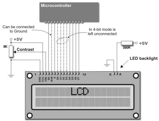
Data is rarely read from the LCD (it is mainly transferred from the microcontroller to the LCD) so it is often possible to save an extra I/O pin by simple connecting the R/W pin to the Ground. Such a saving has its price. Messages will be normally displayed, but it will not be possible to read the busy flag since it is not possible to read the display either. Fortunately, there is a simple solution. After sending a character or a command it is important to give the LCD enough time to do its job. Owing to the fact that the execution of a command may last for approximately 1.64mS, it will be sufficient to wait about 2mS for the LCD.
We are LCD module manufacturer in China and we are supplying Graphic LCD display Module & Character LCDdisplay Module, Dot Matrix LCD display Module etc.
ReplyDeleteGreat article, thanks for sharing such a nice article. Am a great fan of your blog, I Appreciate you to write more interesting articles about bar lcd.
ReplyDeleteCharacter Lcd Basics >>>>> Download Now
ReplyDelete>>>>> Download Full
Character Lcd Basics >>>>> Download LINK
>>>>> Download Now
Character Lcd Basics >>>>> Download Full
>>>>> Download LINK QS