
Smart Cap – DIY Head Mounted Display Project


Head mounted displays are definitely the latest fad that’s going around town now. You might have seen several wearable displays such as the google glass, and many others including virtual reality systems like the oculus rift. Head mounted displays are primarily used for video sharing, navigation, checking notifications, etc. However, several pioneers argue that the quintessential use for it have not yet been identified. But, if you ever wanted to build one for yourself from scratch, and are not willing to pay 1500$ just to experience its functionalities, then this DIY Head Mounted Display project is for you.
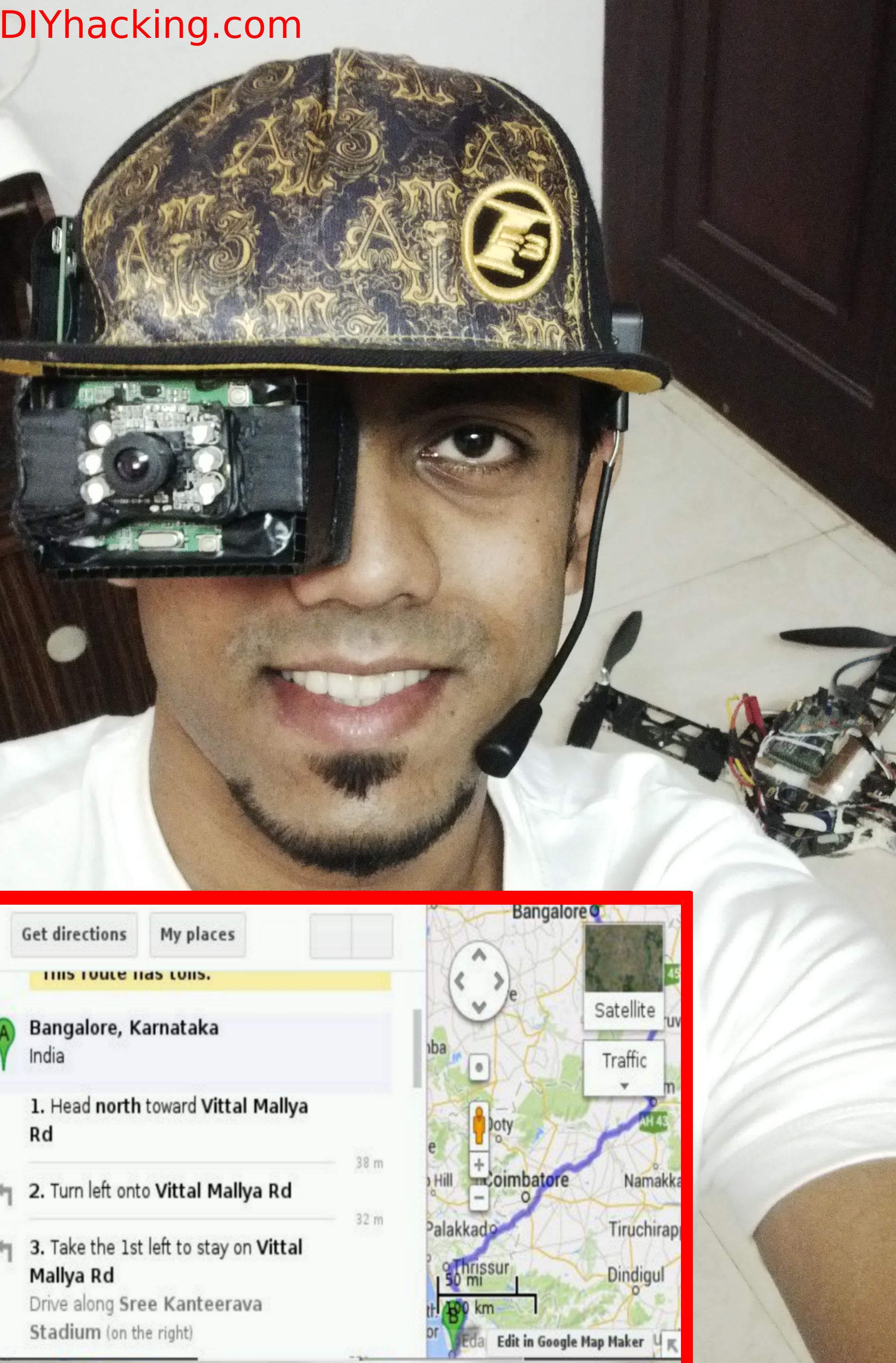
This DIY hacking tutorial will show you how you can make your own head mounted , virtual reality or augmented reality displays. I have built a “Smart Cap” , first of its kind , having a head mounted display on it. Here, I will instruct on how to build a monocular wearable display that runs on the raspberry pi as seen in the picture above. The system includes a webcam for video sharing and recording and also incorporates voice recognition for a hands free experience. Thus, you will be able to build an interactive voice recognition based wearable display at the end of this tutorial.
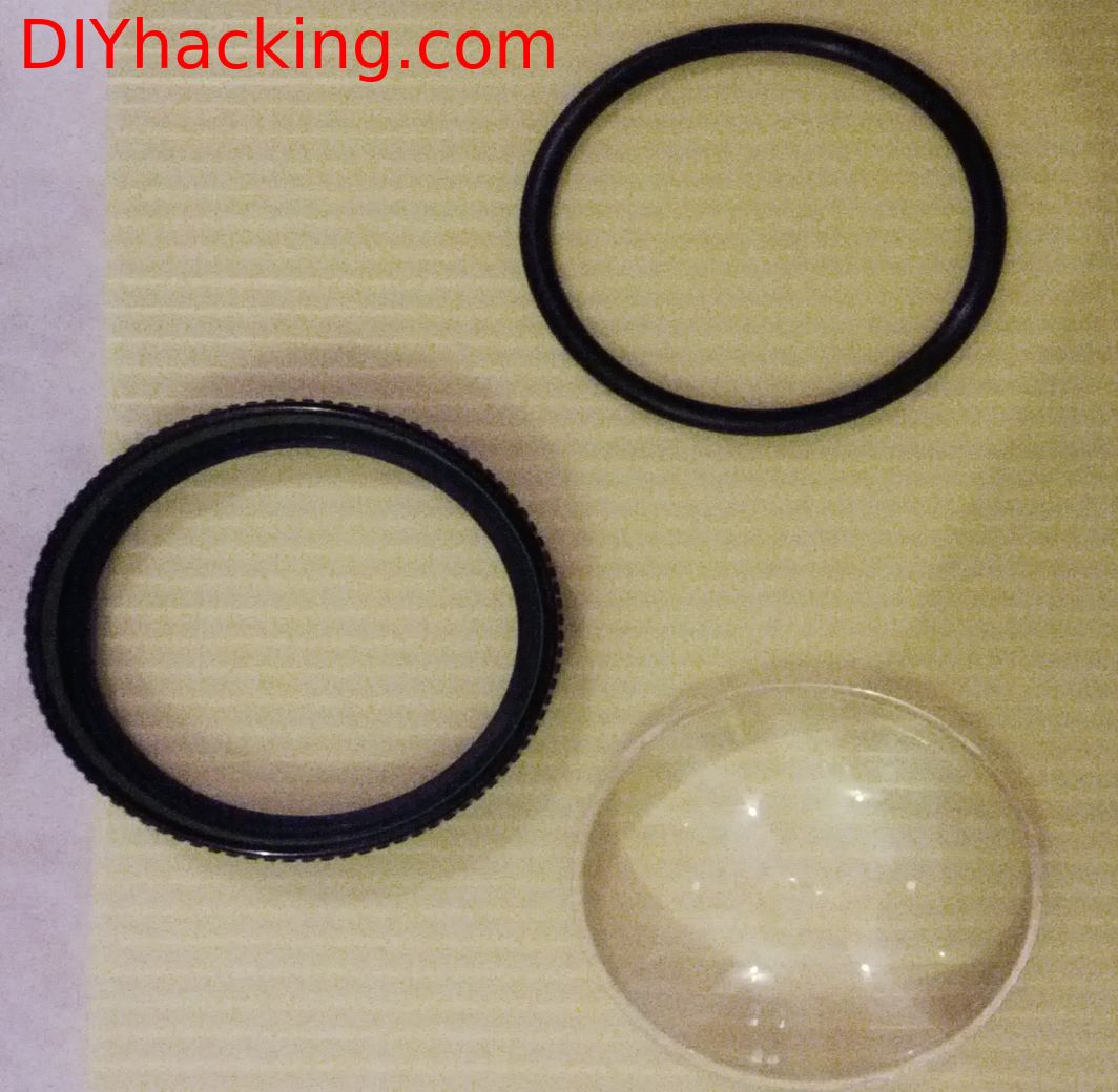
Smart Cap DIY Head Mounted Display Project DIY Hacking
Aspheric Lens
What are the stuff required to do this project?
Hardware:
  1. Raspberry Pi model B.
  2. A USB webcam with an inbuilt mic, I am using one from Iball.
  3. A 2.5″ NTSC/PAL LCD display.
  4. A headphone with mic.
  5. A loupe magnifier with aspheric lens.
  6. Sun board sheets or cardboard sheets.
  7. Fevicol SR glue or equivalent.
Software:
  1. Rasbi OS image with Voice Recognition Software.
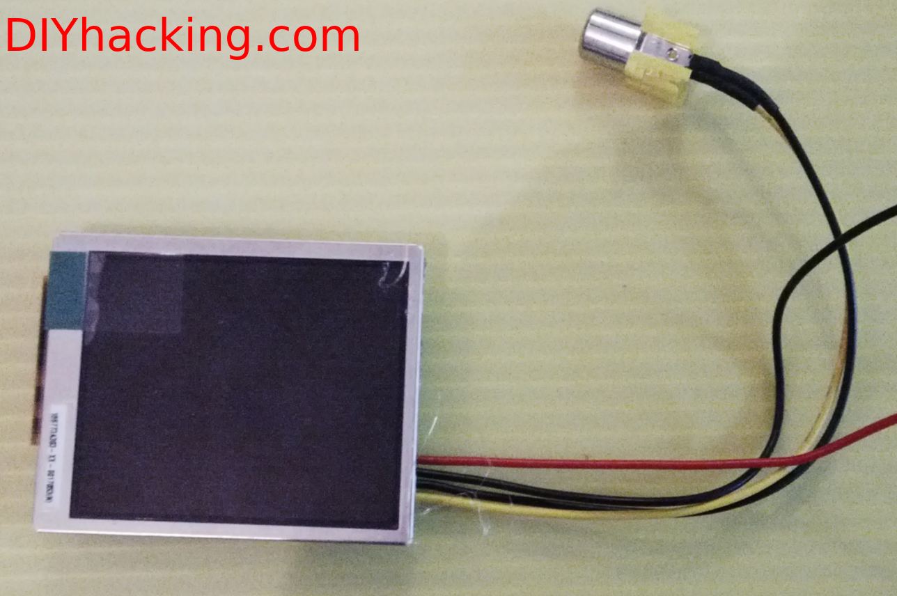
How does it work?
Smart Cap DIY Head Mounted Display Project DIY Hacking
2.5″ LCD Display
Head mounted displays usually consists of a high resolution LCD or any other display screen within about 5-10 cm in front of your eyes. For virtual reality systems, usually one split display or two identical displays are used for each of your eyes for the stereoscopic effect. Here, I am only using one miniature LCD display in front of an eye , hence called a  monocular head mounted display.
In this system , in order to cope with the “Least distance of distinct vision” , which is about 15-25 cm , I have used an aspheric loupe magnifier lens having 5X magnification. This makes it possible for me to see the screen impeccably at about 5-6 cm from my eye. The display is also completely enclosed and insulated from outside light. The next part of the system is a normal USB webcam which was cannibalized to take only the camera and the microphone. All the plastic enclosures of it was removed, and the wires were re soldered to get a niche position for the camera and microphone on the cap. Furthermore, I used a raspberry pi running a voice recognition software I engineered , to ensure hands free operation.
DIY Head Mounted Display Project DIY Hacking
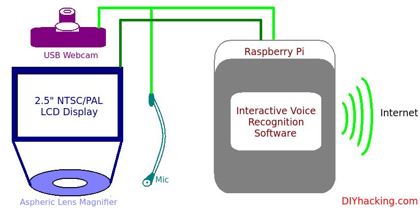
Working of the DIY Head Mounted Display
Here, the LCD display acts like any other PC display. However, when certain voice commands are executed in tandem with the system, appropriate results or data is displayed in front of your eye. A few of those examples are : email , maps for navigation, Google search, YouTube, webcam recording and first person viewing of other cameras, etc. The raspberry pi integrated with this head mounted display thus has to be connected to the internet for performing these functions.


Read More

Comments

Popular posts from this blog

PIC 16F877A Microcontroller Based Electronic Lock 16x2LCD 4x3 Keypad

 Circuit Diagram Security is a prime concern in our day-today life. Everyone wants to be as much secure as possible. An access control for doors forms a vital link in a security chain. The microcontroller based digital lock for Doors is an access control system that allows only authorized persons to access a restricted area. An electronic lock or digital lock is a device which has an electronic control assembly attached to it. They are provided with an access control system. This system allows the user to unlock the device with a password. The password is entered by making use of a keypad. The user can also set his password to ensure better protection. The major components include a Keypad, LCD and the controller PIC16F877A. This article describes the making of an electronic code lock using the 16F877A microcontroller. The system is fully controlled by the 8 bit microcontroller 16F877A which has a 8Kbytes of ROM for the program memory. The password is stored in the

Electronic Voting Machine Using 8051 Microcontroller (AT89C51)

  Circuit Electronic voting machine has now replaced the traditional mechanism of voting due to several advantages like security, automatic counting etc. This project presents a way to develop an electronic voting machine which displays the count of votes on a 16x2 LCD interface. A user can get his/her vote register through a set of switches (one for each candidate). After every cast of vote, the subsequent count can be seen on LCD. The circuit uses AT89C51 microcontroller and the code for the project has been written in C. This LCD based electronic voting machine is designed for four candidates. The input part consists of a set of six tactile switches. The switches and 16x2 LCD are interfaced to microcontroller AT89C51 for various operations and displays. The provision of casting votes for the candidates has been provided through four of these switches. These switches are made active high and connected to pins 2-5 (P1^1 – P1^4) of the controller. The remaining two

89C51 Based Digital Thermometer Using DS1820

Introduction The hardware configuration when using multiple 1-Wire temperature sensors like the DS1820 is very simple, as illustrated in the block diagram below. A single-wire bus is used for communication between the microcontroller and the temperature sensor. It is also possible to power the devices direclty via this 1-Wire bus. An almost unlimited number of 1-WireTM devices can be connected to the bus because each device has a unique 64-bit ROM code identifier which is used to address each sensor   Temperature measurement using DS1820 sensor. Use of ‘1-wire’ protocol... Temperature measurement is one of the most common tasks performed by the microcontroller. A DS1820 sensor is used for measurement here. It is capable of measuring temperature in the range of -55 °C to 125 °C with 0.5 °C accuracy. For the purpose of transferring data to the microcontroller, a special type of serial communication called 1-wire is used. Due to a simple and wide use of these sensors, commands us