 |
| Interrupt of PIC 16F877A |
Features of the external interrupt that we will use.
The interrupt is triggered by an input on RB0, either ( depending on how we set it up ) as the signal goes from 0 to 1, called the rising edge, or as the signal goes from 1 to 0, called the falling edge. This sets the interrupt flag, and if the interrupt is enabled ( and we are not already in an interrupt ) the microcontroller goes to the interrupt subroutine.
The use of the RB0/Int to manage interrupt externally generated requires the setting of a couple of registers of the picmicro: INTCON and OPTION_REG

It should be clear that the use of RB0/Int function of a picmicro requires the setting of the:
GIE(7): set to 1 to enable global interrupts
INTE(4): set to 1 to enable interrupts on pin RB0
PEIE(6): to disable other periferal interrupts
and the set of the INTEDG bit(6) of the OPTION_REG register simply to select the rising or falling edge, of the signal.
When switch is pressed RB0 goes from 0 to 1 causing an interrupt
which calls the interrupt() routine. The interrupt routine increment the value
of PORD by one.
Code
void interrupt(void)
{
PORTD++; //Increment PORTD value by one
//delay_ms(500);
INTCON.INTF = 0; // clear the interrupt flag
}
void main(void)
{
TRISB = 0x01;
TRISD = 0x00;
INTCON.GIE = 1; //Enable Global Interrupt
INTCON.INTE = 1; //Enable RB0/INT external
Interrupt
INTCON.PEIE = 0; //Disable all unmasked
peripheral interrupt
OPTION_REG.INTEDG = 1; //Interrupt on rising edge
PORTD=0;
do
{
} while(1);
}
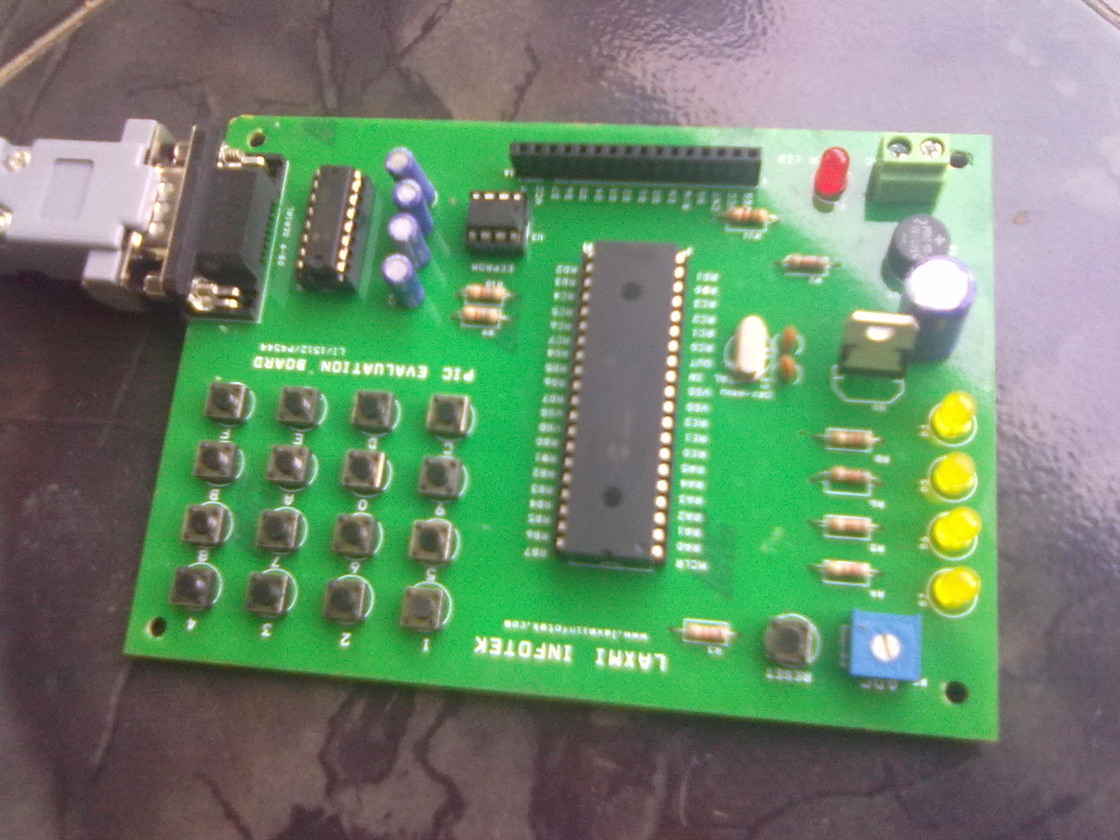
Circuit
 |
| Interrupt of PIC 16F877A |
Hi, you can simplify the HW and thereby save R2 by configuring RBPU (Pullups on Port B) and using the switch to pull RB0 to GND instead to Vcc.
ReplyDeleteThen INTEDG needs to be set to zero to interrupt on keypress.
With your HW you can simplify the SW. INTEDG is set to 1 on Reset - so "OPTION_REG.INTEDG = 1;" not needed
Nice information about the microcontrollers which comes under embedded projects. PIC microcontrollers are used to perform various number of tasks. They are used in alarms,control systems,phones,etc. This microcontroller has special features such as flash memory, Data SRAM, Data EEPROM, Watchdog Timer,etc.
ReplyDelete